A rover robot has been an ongoing project for several years.
I have been evolving it as I find things that can not be expanded upon easily, or as the technology goes obsolete.
The very first version used the standard Tamiyama tank treads and a pic microcontroller.
 The little tank has line following sensors and a bumper for colision detection. The gearbox on the robot was WAY louder than I found acceptable, so it sits on a shelf. Besides this, the tank treads are not realyy very all terrain: the would get clogged with grass if it is more than halfway up the treads.
From there I built a small 3 wheeled robot that could follow lines, sense nearby objects, and scoot around fairly quickly.
I will post the pictures if I find them. The gearboxes on the little scooter were far quieter. I now use better quality gearboxes.
The next iteration was the first try at my new plan for making it useful: using a metal detector and magnetometer to drive around and map an area underground.
The bit on the tower indicates the direction that the robot thinks is north. It turns out that using a compass around electric motors is not quite as simple as it seems: I had to use some sensor fusion techniques to mix the gyroscope data with the compass data to keep a true north. The wheel lying in the foreground is an example of the origional wheels the rover was using. The frame is welded and machined aluminum channel with a largish scale RC truggy suspension, and scratch built steering linkages. The controller was an ET-ARM stamp using an LPC2119 at something like 80MHz.
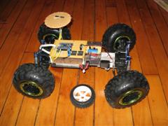
 The current version is built around actobotics aluminum extrusions.
 It has a spine of 1.5x 1.5 x 12" u channel, four wheel steering and individually controlled wheel motors. The steering feedback is achieved by installing a small diametric ring magnet inside the worm gear box that drives the steering axis and reading that with a magnetic encoder sensor.
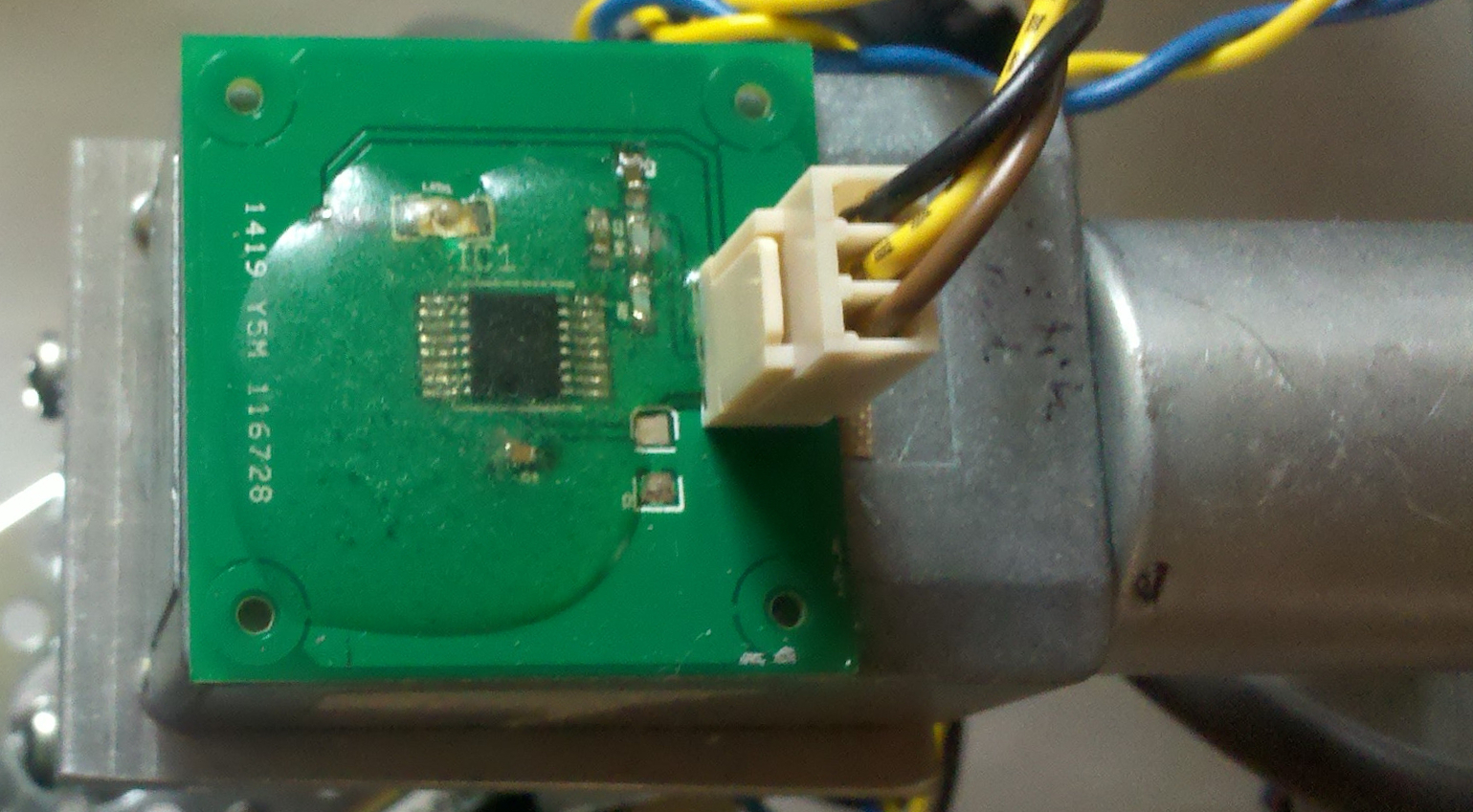 Drive wheel speed is PID controlled based on the encoder feedback from the drive gear motors. The drive wheels are recycled from a previous iteration of the robot rover, and the drive shafts are machined from 2020 aluminum stock, as are the shaft extensions that attach the drive box to the steering worm drive. The shaft extensions on both drive shafts allow for the addition of bearings to support the load end of the shafts and to isolate the gearboxes from outside loads somewhat.
So far the controls consist of 4 controllers based on ATMEG328 controllers that control the speed and direction of each wheel. These are temporarilly controlled by by an ATMEGA1280 based arduino board; my plan is to migrate the maser controller to a PCDuino controller which has significantly more powerful dual core ARM processor, a gig of ram, and improved storage and communication options, as well as built in WiFi.
The sensor suite so far consists of encoders on all the wheels for speed and distance feedback, magnetic encoders on all of the steering gearboxes for direectional feedback, an 'optical flow' sensor in the center of the spine looking down as additional speed and direction feedback, there sill be 3 axis magnetometer, 3 axis gyro, and 3 axis accelerometer sensors integrated shortly. I am thinking of adding either a sonar sensor on a directional scanning mount, or a set of 4 sonar sensors for detecting obstacles. I may also integrate a line laser and camera based parallax sensor that I built for a previous version.
All of the robot pictures were uploaded as full size and scaled using your browser. Right-clicking on any of them and selecting view will open the full sized picture for detailed inspection: if you were to open the first of the new rbot pictures and look at the bottom right steering gearbox, you would see a small magnet sitting on the gearbox that was being used to test the magnetic encoder concept.